How welding affects steel strength is not a simple question of whether a joint becomes stronger or weaker. A weld creates a small, intense thermal cycle. Near the seam, the heat-affected zone may develop a different microstructure from the untouched plate. Grain growth, rapid cooling, residual stress, and weld defects can all influence performance. The result depends on the steel grade, filler metal, joint design, heat input, and cooling conditions. Details matter.
Welding metallurgy expert John C. Lippold’s published work emphasizes the relationship between material behavior and the welding process. In paraphrase, his central point is: “A weld’s performance depends on both the material and its thermal history.” That distinction helps explain why two welds on similar-looking steel can behave differently under load. A thick plate may cool unlike a thin one; a rushed pass may leave stress or inconsistent fusion. Even a sound-looking bead needs proper inspection. Appearance alone is not proof.
This introduction examines how welding affects steel strength through changes in the weld metal, heat-affected zone, and surrounding base metal. It also considers hardness, ductility, toughness, and practical testing. No single rule fits every steel or application. That is easy to overlook. Engineers and qualified welding professionals assess the material, procedure, service conditions, and inspection results together. The goal is not merely a strong seam, but a reliable joint whose behavior suits its intended use.
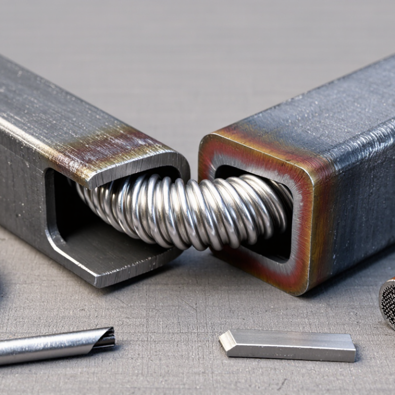
How Does Welding Affect Steel Strength?
Welding does more than join two steel edges. It creates a small region where heat changes the metal. The area directly beneath the arc melts, then solidifies into weld metal. Its grain pattern can differ from the steel around it. Heat travels.
Beside the weld lies the heat-affected zone, or HAZ. This steel does not melt, but it experiences a steep temperature cycle. Near the weld, grains may grow larger; farther away, the structure may change less. In some carbon steels, fast cooling can form harder, less ductile areas. The exact result depends on steel composition, thickness, heat input, and cooling conditions. Cooling rate matters. A description on a diagram can look tidy; the real boundary is uneven.
These structural changes can affect strength, toughness, and fatigue performance. A weld may be strong while its HAZ becomes the more vulnerable spot, especially under repeated loading. Heating and uneven cooling can also leave residual stresses or pull a plate out of alignment. Preheating, controlled welding speed, and suitable filler material can help manage these effects, but they are not automatic fixes. Inspecting the joint and considering the steel grade matter. In a thick plate, for example, the surface may cool differently from the interior, so one simple rule may not fit every weld.
Heat input shapes both the weld metal and the heat-affected zone, the base steel beside the weld that never melts. It depends on current, voltage, travel speed, and welding process. A slow pass can put more energy into each inch.
That matters.
In some steels, excessive heat can widen the HAZ and encourage grain growth, reducing toughness. A large, slow-cooling weld may also increase distortion. But lower heat is not automatically better. Fast cooling can create hard, brittle regions in susceptible steels, especially when thickness or restraint is high.
The right balance depends on the steel grade, joint design, preheat, and filler metal.
On a thick plate, the weld face may look sound while the HAZ tells a different story. Small details count. Consistent travel speed and suitable interpass temperatures help control variation between passes.
Heat-input calculations are useful, but they do not describe every real-world condition; fit-up, restraint, and cooling all matter. I would not judge a procedure by appearance alone. Check the qualified welding procedure and, where required, use hardness or toughness testing to assess the finished joint.
Welding changes steel locally, not uniformly. The weld metal melts and solidifies, while nearby steel forms a heat-affected zone (HAZ). Its grain size and hardness depend on the steel grade, heat input, and cooling rate. A fast-cooling HAZ may become hard and less tolerant of cracking; excessive heat can soften some high-strength steels. The effect is specific to the material and procedure. There is no single strength penalty.
Toughness needs direct testing. ASTM E23 specifies a standard Charpy V-notch specimen measuring 10 × 10 × 55 mm; absorbed energy is reported in joules. That number helps compare impact resistance at a stated temperature, but it does not predict every service condition. The International Institute of Welding’s fatigue recommendations also classify welded details by joint geometry and stress range, rather than relying on base-metal strength alone. In practice, a thick plate’s weld toe, root, and HAZ deserve close inspection. Weld quality matters. So does restraint. I have seen “stronger steel” treated as a guarantee, and that is a shaky assumption. Procedure qualification, hardness checks, and impact tests can reveal trade-offs, though test results still need careful interpretation.
Welded steel strength depends on more than the filler metal. Joint design, base-metal grade, weld size, and loading direction all matter. ANSI/AISC 360-22 uses 0.60 times the electrode classification strength for fillet-weld nominal stress, applied across the effective throat area. A smaller throat means less load-carrying area. Poor fit-up can make that shortfall hard to spot. Heat input and cooling rate also affect the heat-affected zone, where steel properties may change. Small details matter.
Fatigue performance depends strongly on weld shape and location. The International Institute of Welding’s 2016 recommendations classify welded details by stress range at two million cycles; for example, FAT 80 represents 80 MPa at that reference life. It is not a universal weld-strength value. A toe notch, undercut, or abrupt change in section can concentrate stress there. For a joint exposed to repeated vibration, inspection and fatigue assessment deserve close attention. The American Welding Society’s Structural Welding Code—Steel, AWS D1.1/D1.1M, provides qualification and workmanship requirements, but a compliant weld can still be poorly suited to its actual loading. That distinction is easy to miss. Repair history, restraint, and measured weld dimensions should inform the assessment; relying on visual appearance alone leaves uncertainty.
Evaluating welded steel means testing the joint, not just the parent plate. A tensile test can show whether failure starts in weld metal, the heat-affected zone, or base steel. Bend tests expose surface cracks; macroetch sections reveal penetration, fusion, and root defects. For fatigue-critical details, the International Institute of Welding’s 2016 fatigue recommendations classify joints by FAT strength. FAT 80 represents a characteristic stress range of 80 MPa at two million cycles. That is a design category, not a guarantee for every weld. Small toe notches matter.
Inspectors combine mechanical tests with visual examination and suitable nondestructive methods, such as ultrasonic or radiographic testing. The choice depends on joint geometry. Hardness measurements across the weld and heat-affected zone can flag local hardening, while Charpy V-notch tests assess impact toughness at specified temperatures. ASTM E8/E8M describes tensile testing of metallic materials; reports should record specimen location, orientation, and failure position. I would not trust one polished coupon alone. Structures experience restraint, residual stress, and variable loads. Representative qualification samples and documented inspections provide a better picture, though sampling still leaves uncertainty.
| Evaluation method | Property or feature measured | What the results can show | How welding can affect the result | Relevant test standard |
|---|---|---|---|---|
| Transverse weld tensile test | Ultimate tensile strength of a specimen containing the weld; fracture location may also be recorded. | Shows the tensile performance of the welded joint as a whole. Strength is commonly reported in MPa. | A joint may fail in the weld metal, heat-affected zone (HAZ), or base metal. The result depends on the steel, filler metal, joint design, welding procedure, and specimen geometry. | ISO 4136; ASTM E8/E8M for metallic-material tension testing |
| Guided bend test | Weld and HAZ ductility, together with the presence of surface-breaking discontinuities after bending. | Cracks or openings on the tension face can indicate a lack of soundness or inadequate ductility. Acceptance limits depend on the applicable code or specification. | Weld defects, brittle regions, or poor fusion may become visible during bending. A bend test does not directly measure tensile strength. | ISO 5173; ASTM E190 |
| Charpy V-notch impact test | Energy absorbed by a notched specimen during impact, usually reported in joules at a specified test temperature. | Indicates resistance to impact fracture under the test conditions; it is useful for comparing toughness at specified temperatures. | Welding can create local toughness differences in the weld metal and HAZ. Results depend on notch location, temperature, specimen size, and material condition. | ISO 9016; ASTM E23 |
| Hardness traverse across the joint | Local resistance to indentation measured across weld metal, HAZ, and base metal. | A hardness profile helps identify local hardening or softening. Hardness alone does not establish tensile strength or fracture toughness. | Rapid cooling may produce harder microstructures in some steels, while thermal exposure can soften certain heat-treated steels. The response varies with composition and welding conditions. | ISO 9015-1; ISO 6507-1 for Vickers hardness; ASTM E384 for microindentation hardness |
| Macrographic examination | Weld cross-section features, including penetration, fusion boundaries, weld profile, and visible discontinuities. | Reveals the weld’s overall geometry and can help identify incomplete penetration, lack of fusion, or other section-level features. | It can show whether the joint was fused as intended, but a single section represents only the location examined and does not quantify mechanical strength. | ISO 17639; ASTM E340 |
| Ultrasonic testing (UT) | Internal reflectors that may be associated with discontinuities, using sound waves introduced into the weld. | Can help locate and assess relevant internal indications when the procedure and personnel are qualified for the joint. | Findings depend on joint geometry, material, probe setup, calibration, and flaw orientation. UT is an examination method, not a direct strength measurement. | ISO 17640; ASTM E164 |
| Radiographic testing (RT) | Differences in transmitted radiation through the weld, recorded as an image. | May reveal volumetric discontinuities such as porosity and some forms of slag inclusion, depending on their size and orientation. | Radiographic visibility depends on discontinuity orientation and thickness. RT does not directly measure strength and may be less sensitive to tight planar flaws aligned with the beam. | ISO 17636-1; ASTM E1742/E1742M |
| Welded-joint strength comparison | Measured transverse tensile strength compared with the specified minimum tensile strength of the base material. | A comparison can summarize joint tensile performance. One commonly used calculation is: joint efficiency (%) = measured joint tensile strength ÷ specified base-metal tensile strength × 100. | The calculated percentage is a comparison, not a universal acceptance criterion. The required result must come from the governing design code, material specification, or qualification procedure. | Based on tensile-test results; acceptance requirements are specification-dependent |
| Interpretation note: Welding does not produce one predictable strength change for all steels. Strength and toughness depend on the steel grade, weld metal, heat input, cooling conditions, joint design, and any preheat or post-weld heat treatment. Test results should be interpreted against the applicable material specification and construction code. | ||||
Joint design, base-metal grade, weld size, and loading direction all matter. Filler metal is only part of the picture.
It is the weld area that carries load. A smaller throat provides less area, and poor fit-up can hide the shortfall.
No. Weld shape and location affect fatigue performance. A small notch at the weld toe can concentrate stress under repeated vibration.
It represents a characteristic stress range of 80 MPa at two million cycles. It is a design category, not a promise for every joint.
Tensile and bend tests show how a joint responds to loading. Macroetch sections can reveal penetration, fusion, and root defects. No single test tells the whole story.
They may use visual checks, ultrasonic or radiographic testing, and hardness measurements. The suitable method depends on joint geometry.
Yes. A weld may meet workmanship requirements but perform poorly under its actual loading. That distinction is easy to overlook.
Measured weld dimensions, repair history, restraint, and expected loads help. One polished test coupon is useful, but it cannot represent every condition. Uncertainty remains.
Welding changes steel by creating a melted and fused region alongside a heat-affected zone, where the metal’s original structure may be altered even though it has not melted. The amount of heat introduced, how quickly the joint cools, and the steel’s composition can influence grain structure and hardness. These changes may increase strength in some areas, but they can also reduce toughness or create uneven properties across the joint. Understanding how welding affects steel strength therefore requires looking at the weld metal and surrounding steel as a combined system.
The performance of welded steel depends on factors such as joint design, welding procedure, heat input, cooling conditions, and preparation of the steel. Appropriate methods for evaluating a finished joint include visual inspection, mechanical testing, and examination for internal or surface defects. Together, these checks help determine whether the weld can carry its intended loads while maintaining adequate strength and toughness.

Sandstorm Steel