Choosing a steel fabrication method is not simply a matter of picking the fastest machine. The right process depends on the part’s shape, steel grade, thickness, required tolerances, production volume, and budget. A thin mounting plate may suit laser cutting, while a heavy structural bracket could need plasma cutting and careful welding. Small details matter. A narrow slot, for example, can affect both cutting time and edge quality.
So, what are common steel fabrication methods, and how do they fit different projects? Typical options include cutting by laser, plasma, waterjet, or sawing; forming with press brakes or rolls; and joining through welding or mechanical fastening. Machining may also be needed when holes, threads, or close-fit surfaces must meet precise specifications. Each method brings trade-offs. Laser cutting can produce clean, detailed profiles, but may not be the economical choice for every thick section or large order. Welding offers strong, flexible joints, though heat can cause distortion if the part is not planned carefully.
A reliable choice starts with the drawing and the real conditions of use. Check load requirements, finish expectations, assembly access, and inspection needs with a qualified fabricator. Ask how the process affects lead time, material waste, and later repairs. There is no perfect route. A clean CAD model can still miss a practical issue, such as a weld that is difficult to reach. Comparing methods early can prevent costly revisions, though the final decision may require a sample or design review.
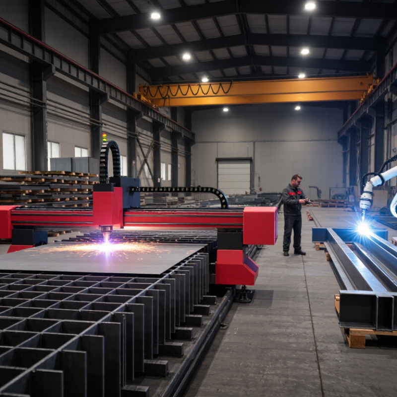
Before choosing a steel fabrication method, confirm the grade and measured thickness. ASTM A36 is commonly specified with a minimum yield strength of 36 ksi for material up to 8 inches thick; thicker material may have a lower specified minimum. Yield strength describes when steel begins to deform permanently, not its ultimate tensile strength. Check the applicable material specification and mill test report rather than relying on a grade label alone.
Thickness affects both fabrication and fit-up. A 1/4-inch A36 plate may be cut and welded differently from a 2-inch plate, which needs more heat and careful joint preparation. For example, a shop may use laser or plasma cutting on thinner sections, while thicker plate may suit other cutting methods. The best choice depends on required edge quality, tolerances, production volume, and available equipment. Small details matter.
A36 is generally weldable, but joint design, restraint, and cooling conditions still influence results. A tight corner on a thick bracket can concentrate stress, even when the material meets its grade requirements. I would verify the drawing dimensions and intended loads before settling on a process. That choice is not always obvious. It can be tempting to select the fastest cutting method, then discover that extra cleanup or distortion control erases the time saved.
Laser and plasma both cut steel, but their useful thickness ranges differ. TWI’s technical guidance places industrial laser cutting near 25 mm for many applications. The AWS Welding Handbook describes plasma-arc cutting as suitable for much thicker plate; systems can exceed 50 mm. These are practical ranges, not guarantees. Steel grade, power, nozzle condition, and cut speed all affect results. A 25 mm laser-cut edge may be clean and precise, while a plasma-cut edge on 50 mm plate may need grinding. Thick plate is slower. That matters.
Tips: Check the machine’s rated capacity and sample-cut your actual steel. Ask for the required edge tolerance, too. Plasma’s higher capacity can bring a wider kerf and more heat distortion; laser may struggle as thickness approaches its practical limit. Compare total cost, including finishing and scrap—not just cutting speed. And inspect the underside. Dross can hide there.
The ranges describe capability, not quality at every thickness. A shop’s setup and operator experience matter, and published limits may not reflect your material. I would not choose from the headline number alone. Ask for a test cut in the same grade and thickness, then measure the edge and fit-up.
For mild steel, an inside bend radius near 1× sheet thickness is a useful starting point—not a guaranteed minimum. A 2 mm sheet might begin testing near a 2 mm radius. The ASM Handbook, Volume 14B, Metalworking: Sheet Forming, identifies material ductility, thickness, and forming conditions as key influences on bendability. In the shop, check the steel grade and grain direction before fixing tooling. A tight radius can cause cracking, especially across the grain or near sheared edges. Small details matter.
Treat the 1× ratio as a trial value, then confirm it with a sample bend. The American Iron and Steel Institute’s AISI S100-16 design provisions account for material properties and formed geometry in cold-formed steel design; they do not make one radius suitable for every sheet. Inspect the outside bend under good light for fine cracks, and measure the inside radius after springback. If the part has holes near the bend, check their distortion too. A larger radius may reduce cracking but change fit, flange length, or assembly clearance. It is easy to overfocus on the number. Record the actual radius, thickness, tooling, and results, then adjust the next run.
Select forming by geometry: for mild steel, an inside bend radius often starts near 1× the material thickness.
This 1× relationship is a starting guideline, not a universal minimum. The achievable radius depends on the steel grade, tooling, bend method, and direction of the material grain; confirm requirements with your fabricator.
How to Choose the Right Steel Fabrication Method?
Match the welding process to the joint, access, and AWS D1.1 requirements—not just production speed. For a long, accessible fillet weld, GMAW or FCAW may support steady shop production. A tight corner, awkward position, or field repair may favor a process qualified for those conditions. Check the drawing’s weld type, size, position, and base-metal details before setting parameters. AWS D1.1/D1.1M sets requirements for structural-steel welding, including procedure and welder qualification, inspection, and acceptance. Confirm the project’s specified edition and contract documents; a familiar process is not automatically approved.
Fit-up matters. A visible root gap, mill scale, or poor access can affect penetration and weld quality, even when the machine settings look correct. Match the joint preparation and welding procedure to the actual assembly, then verify the procedure covers the process, material, thickness, and position. The American Welding Society’s 2023 workforce report projected 330,000 new welding professionals would be needed by 2028. That makes clear procedures and repeatable setups especially practical, though training cannot replace inspection. I’d still question a method chosen only because it is faster; the real bottleneck may be fit-up.
Tips: Before production, make a trial weld on representative material. Check access, distortion, and required inspection points. Record the approved settings, and revisit them when the joint changes.
| Welding Process | Joint Designs and Typical Applications | Access, Position, and Fabrication Fit | Key Advantages | Limitations and Controls | AWS D1.1 Planning Considerations |
|---|---|---|---|---|---|
| SMAW (Shielded Metal Arc Welding) |
Fillet welds on T-, lap, and corner joints; groove welds in butt joints; field connections and repair work. | Portable equipment supports shop and field work. Suitable for many positions when the electrode classification and procedure are appropriate. | Versatile; useful where access, wind exposure, or equipment mobility makes wire-fed processes less practical. | Slag must be removed between passes. Electrode storage and handling matter, and deposition is generally slower than continuous-wire processes. | Check the electrode classification, base-metal group, position, joint details, preheat, and other applicable WPS variables. Use a prequalified WPS only when all applicable D1.1 conditions are met; otherwise, a qualified WPS may be required. |
| GMAW (Gas Metal Arc Welding) |
Production fillet welds and groove welds in shop-fabricated assemblies; commonly used on accessible plate and structural components. | Best suited to controlled shop conditions. Shielding gas and torch access can make outdoor or obstructed work less suitable without appropriate controls. | Continuous wire feed supports high productivity and reduces interpass slag removal compared with flux-covered processes. | Shielding gas can be disturbed by drafts. Fit-up, stickout, travel speed, and transfer mode require consistent control. | Confirm the transfer mode and WPS status. Short-circuiting GMAW has specific code restrictions and should not be assumed to qualify as a prequalified procedure. Verify applicable D1.1 requirements for the selected mode and joint. |
| FCAW (Flux Cored Arc Welding) |
Fillet welds and groove welds in structural assemblies, including beams, columns, and plate components. | Common in shop production and, with suitable equipment and consumables, in field work. Availability of position-rated wire depends on the electrode classification. | High deposition capability; some wires provide shielding from their flux, while gas-shielded variants can offer different operating characteristics. | Slag removal may be needed between passes. Gas-shielded versions are sensitive to wind; fumes and consumable handling require suitable controls. | Match the electrode classification and shielding arrangement to the WPS. Verify position limitations, joint details, preheat, and whether the procedure meets the applicable prequalified-WPS rules or requires qualification. |
| SAW (Submerged Arc Welding) |
Long, continuous groove welds and fillet welds on plate, built-up sections, and repetitive shop assemblies. | Primarily suited to flat or horizontal work in a shop or mechanized setup. The joint and equipment must allow stable travel and flux coverage. | High deposition rates and consistent results on long production welds; the arc is covered by granular flux during welding. | Less adaptable to short, irregular, or out-of-position welds. Slag and unused flux require handling, and setup may be more involved. | Check the applicable process, electrode-flux combination, joint configuration, position, and WPS requirements. Confirm that the proposed joint details and procedure satisfy the applicable D1.1 provisions. |
| GTAW (Gas Tungsten Arc Welding) |
Root passes or specialized welds where precise heat input and puddle control are important; use on structural-steel work depends on project requirements. | Requires clean joint surfaces, good torch access, and shielding-gas protection. Generally more practical for controlled shop work or limited, specialized applications. | Precise control of the arc and filler-metal addition; no flux slag is produced. | Typically slower than production wire processes. Gas shielding is vulnerable to drafts, and operator skill and cleanliness are important. | Do not assume the process or a proposed procedure is prequalified. Check the governing D1.1 edition and project requirements to determine the required WPS qualification and applicable essential variables. |
Code and design note: AWS D1.1 requirements depend on the edition adopted by the contract documents and the specific application. A welding process alone does not establish code compliance. Confirm that the base metal, joint geometry, weld size, backing or backgouging details, position, filler metal, preheat, inspection requirements, and WPS meet the applicable project and code provisions. Where a prequalified WPS is not permitted or its conditions are not satisfied, procedure qualification may be required.
Before choosing a fabrication route, define which dimensions truly matter. A laser-cut plate may hold its profile closely, while a welded frame can move as heat builds. Put critical dimensions, datums, and acceptable variation on the drawing. Ask the shop how it will inspect them, not just whether it can meet them. That matters. Check the tolerance stack across parts that must fit together; a small mismatch can complicate assembly.
Production volume changes the cost equation. Laser cutting and press braking often suit repeatable sheet-metal runs, while machining may make sense for parts needing tight features or detailed surfaces. For a small batch, setup and programming can outweigh the unit price. For larger runs, tooling, cycle time, and material waste deserve closer attention. Tiny orders behave differently. Request quotes at more than one quantity, and include finishing, inspection, packaging, and delivery. A low piece price can hide extra work.
Compare the routes using the same drawing and requirements. Confirm material grade, thickness, finish, and tolerances before comparing estimates. A tidy spreadsheet can still miss rework risk or a difficult weld access point. It is worth asking for a prototype when fit is uncertain, though prototypes add time and cost. Estimates may change once the shop reviews the details; that is a useful warning, not necessarily a problem.
It is the minimum specified yield strength for material up to 8 inches thick. Yield strength marks when steel begins to deform permanently. It is not ultimate tensile strength.
Not by itself. Check the material specification and mill test report, especially for thicker material.
A 1/4-inch plate may need different cutting and welding settings than a 2-inch plate. Thicker steel often needs more heat and careful joint preparation.
Consider edge quality, tolerances, production volume, and available equipment. A fast cut may need extra cleanup. That can erase the time saved.
Yes, but joint design, restraint, and cooling conditions still matter. A tight corner on a thick bracket can concentrate stress.
Try an inside radius near one times the sheet thickness. For 2 mm sheet, test near a 2 mm radius. It is only a starting point.
Make a sample bend and inspect its outside surface under good light. Look for fine cracks, then measure the inside radius after springback.
Check whether nearby holes have distorted. Record the thickness, grain direction, tooling, and measured radius. I might still miss a setup detail, so keep the sample for comparison.
Choosing the right steel fabrication method starts with the material. Confirm the steel grade and thickness, since these affect strength, formability, and the processes available. For example, ASTM A36 has a minimum yield strength of 36 ksi. Compare cutting options against the job’s requirements: laser cutting is commonly suited to material up to about 25 mm thick, while plasma can handle sections exceeding 50 mm. These limits can vary with equipment and the desired edge quality.
Next, match forming and welding to the part’s geometry and joint design. Mild-steel bends often start with an inside radius near one times the material thickness, but the final choice depends on the steel and tooling. Welding should meet the relevant structural requirements, such as AWS D1.1, where applicable. When considering what are common steel fabrication methods, weigh tolerances, production volume, and total cost alongside technical fit. Reviewing these factors together helps identify a fabrication route that produces reliable parts without unnecessary steps or expense.

Sandstorm Steel